Once all the hardware peripherals are connected to cabinet,
the most important and final part of assembling computer is providing proper
power connection to the motherboard and other hardware peripherals.
Power connections from SMPS to motherboard and other
hardware peripherals is very crucial. The 20 or 24 pin power connector and one 4 pin
power connector which comes from SMPS has to be fixed to motherboard.

Both 20 or 24 pin and 4 pin power connectors have a lock.

Not all motherboards have 24 pin power connector. Some motherboards will have only 20 pin power connectors.

Look
for the 20 or 24 pin power connector on the motherboard and connect the 20 or 24 pin power connector from SMPS to
motherboard as shown in the below image.

Now connect
the 4 pin power connector from SMPS to
the 4 pin connector of the motherboard as shown in the image.


Note that some older
motherboard will not have the option of providing 4 pin power connector.
All CPU cabinets will have a set of cables or wires such as
power, reset, hard disk LED and power LED, speaker, USB and sound which has to
be connected to motherboard.

The USB and sound cables
are provided only if you have a provision for connecting USB devices and sound
from the front of your cabinet.

Look for the name F_PANEL or FRONT PANEL or PANEL1 on the
motherboard. All motherboard manufacturers name the front panel connections
differently.


The
F_PANEL is a 10 pin connector.
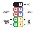
In the F_PANEL you find some
times RST for reset, ON/OFF or PWR_BTN or PWR_SWITCH or PW for power, SPK or
SPEAKER for speaker, HDD_LED or HD_LED or HLED or HD for hard disk drive LED,
POWER_LED or POW_LED or PWR_LED for power LED.
Usually in 10 pin front panel power connector you will
find only 9 pins as shown in the above image. The 9th pin as shown in the above image should be always free. Meaning you should not connect able wire or cable to the 9th pin. The two pins next to the block without pin is for power
connection and the two pins just opposite to two power pins is for reset and two
pins next to reset is for hard disk drive LED and two pins opposite to hard
disk drive LED is for power LED. Not all motherboard manufacturers
will have the above said front panel power connections design. Always refer motherboard
manual for the power connections.
After all the power connections to the motherboard is over
cross check once again with the motherboard manual for front panel connections.
Then plug the power chord from SMPS to the main power supply.